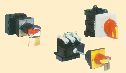
GK20...GK315 rotary switches
|
The structure of a GK switch is different from the KK types. The basic
unit of a GK switch contains three double-breaking contacts moving in
line with the shaft.
The difference in structure refers to different fields at application.
Because of the larger opening clearance the GK switches are
particularly suitable for switch-disconnector and emergency-stop switch
functions but can not be used for example as star-delta motorstarters.
All types are manufactured with 90° switching angle.
|
| Technical data |
GK 20 |
GK 32 |
GK 41 |
GK64 |
GK 80 |
GK 100 |
Rated insulation voltage Ui[V] |
690 |
690 |
690 |
690 |
690 |
690 |
Switchable power
Pe [kW]; (400 V, AC3) |
5,5 |
7,5 |
11 |
18,5 |
22 |
30 |
Conventional free air thermal current [A]
Ith(= Ie400 V, AC-1) |
25 |
32 |
40 |
63 |
80 |
100 |
| Dimensions of front plate [mm] |
30×30 |
30×30 |
48×48 |
48×48 |
64×64 |
64×64 |
| Technical data |
GK
125 |
GK
160 |
GK
250 |
GK
315 |
| Rated insulation voltage Ui [V] |
1000 |
1000 |
1000 |
1000 |
| Switchable power Pe [kW]; (400 V, AC3) |
37 |
45 |
55 |
75 |
Conventional free air thermal current [A]
Ith(= Ie. 400 V, AC-1) |
125 |
160 |
250 |
315 |
| Dimensions of front plate [mm] |
88×88 |
88×88 |
88×88 |
88×88 |
The detailed technical description of the product family is in the printed catalogue
"ROTARY SWITCHES" 1,16 MB
For further information see the
 GANZ KK GANZ KK
Home
Top
|